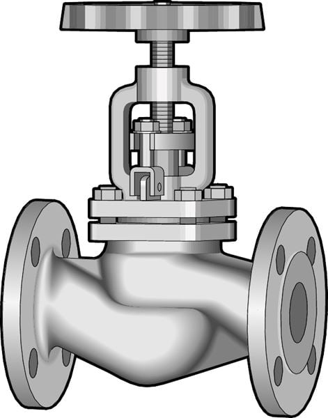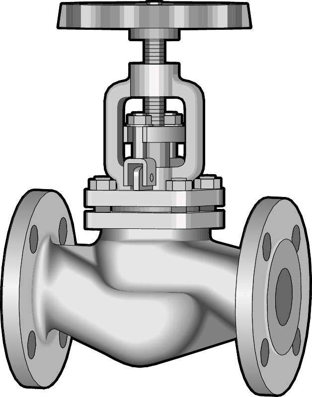
Globe valve made of steel, with flanges, PN 40. With a rising, externally threaded spindle and flat sealing surfaces. Valves, from DN 125 has a pressure-relieved globe/cone as a standard, which means that the direction of the flow is from the opposte side, i.g top and botom. A shut-off valve for steam, condensate and hot water.
| Dimension range | DN 15 to DN 250 |
|---|---|
| PN | 40 |
| Temperature range | -10 °C to +400 ºC |
| Material | Steel |
| Article number | Amount |
|---|---|
| AT 1040C15 | |
| AT 1040C20 | |
| AT 1040C25 | |
| AT 1040C32 | |
| AT 1040C40 | |
| AT 1040C50 | |
| AT 1040C65 | |
| AT 1040C80 | |
| AT 1040C125 | |
| AT 1040C150 | |
| AT 1040C200 | |
| AT 1040C250 |
| Dimension range | PN | Temperature range | Material |
|---|---|---|---|
| DN 15-250 | 40 | -10 ºC to 400 ºC | Steel |

A shut-off valve for:
- Steam
- Hot water
- Condensate
Pressurized parts are manufactured in a foundry, which is generally approved by all recognized classification authorities.
Certificate SS-EN10204, type 2.2 and 3.1, as well as by most classification authorities (type of certificate is to be stated upon ordering). Testing carried out in accordance with DIN EN 12266.
CE-marking
The valves meet the requirements in AFS 2016:1 and 2014/68/EU (Pressure Equipment Directive).

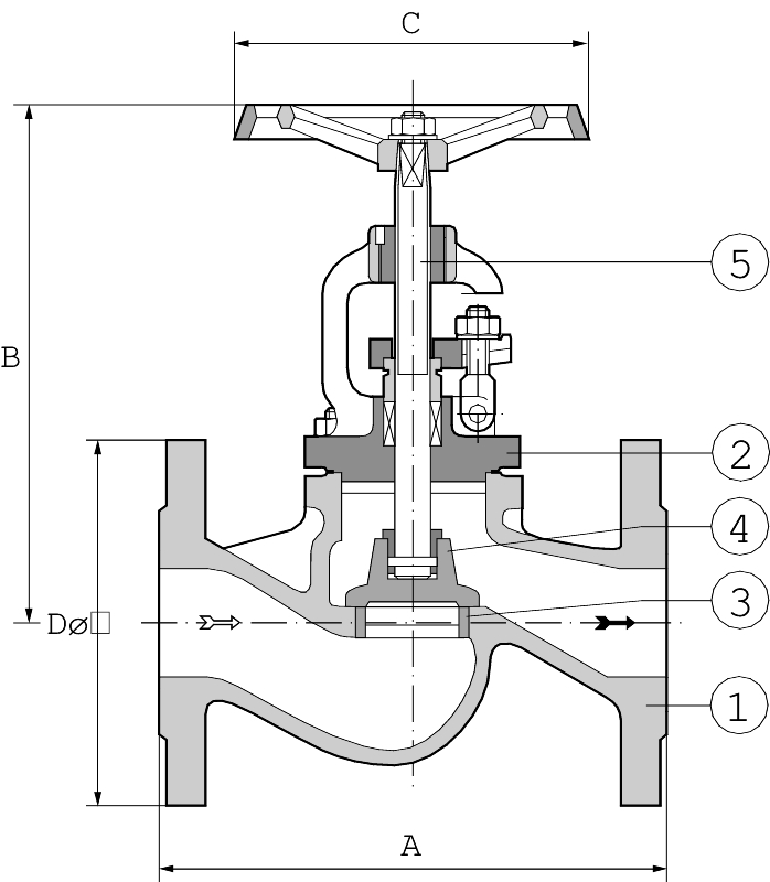
| Pos | Component | Material | ||
|---|---|---|---|---|
| 1 | Body | Steel 1.0619 | ||
| 2 | Bonnet | Steel 1.0619 | ||
| 3 | Seat | Stainless steel 1.4021* | ||
| 4 | Globe | Stainless steel 1.4021* | ||
| 5 | Spindle | Stainless steel 1.4021* | ||
| *At temperatures higher than 350 C, Stellite is recommended | ||||
| DN | 15 | 20 | 25 | 32 | 40 | 50 | 65 | 80 | 100 | 125 | 150 | 200 | 250 | |||||||||||||
|---|---|---|---|---|---|---|---|---|---|---|---|---|---|---|---|---|---|---|---|---|---|---|---|---|---|---|
| A | 130 | 150 | 160 | 180 | 200 | 230 | 290 | 310 | 350 | 400 | 480 | 600 | 730 | |||||||||||||
| B | 185 | 185 | 210 | 210 | 235 | 240 | 290 | 305 | 370 | 400 | 470 | 570 | 625 | |||||||||||||
| C | 120 | 120 | 140 | 140 | 160 | 160 | 180 | 200 | 225 | 225 | 300 | 400 | 400 | |||||||||||||
| D | 95 | 105 | 115 | 140 | 150 | 165 | 185 | 200 | 235 | 270 | 300 | 375 | 450 | |||||||||||||
| Weight | 3,9 | 4,6 | 6,3 | 7,5 | 10,5 | 14 | 21,5 | 26 | 51 | 63,5 | 105 | 175 | 323 | |||||||||||||
| Dimension in mm, weight in kg | ||||||||||||||||||||||||||
Rising, male thread stem. Plane sealing areas.
The stuffing box is not pressurized when the valve is in fully open postion.
| Working pressure max. bar | Working temperature. max. °C |
|---|---|
| 35 | 200 |
| 28 | 300 |
| 21 | 400 |
Pressure Drop
To calculate the pressure drop, the following values are used:
| DN | 15 | 20 | 25 | 32 | 40 | 50 | 65 | 80 | 100 | 125 | 150 | 200 | 250 |
|---|---|---|---|---|---|---|---|---|---|---|---|---|---|
| Kvs | 4,2 | 7,4 | 12 | 19 | 31 | 47 | 77 | 120 | 188 | 288 | 410 | 725 | 1145 |
| DN | 125 | 150 | 200 | 250 | |
|---|---|---|---|---|---|
Differential pressure | 25 | 17 | 10 | 6 |
| Fig.No | DN | Flanges acc. to | Weld ends acc.to |
|---|---|---|---|
| AT 1040C | 15 - 250 | SS 335-PN 40 | DIN 3239 Form D |
- Can be mounted in any position except with handwheel pointing downwards.
- The system has to be flushed clean before startup.
- Valves DN15-100 have a flow direction from bottom to top.
- Valves DN125-150 have a reversed flow direction (eg from top to bottom).
However the flow direction is always marked by an arrow on the body.
| Example: AT 1040C50 | ||||
| AT 1040C | 50 | |||
|---|---|---|---|---|
| Fig. nr. | DN | |||
| RSK-number, see the RSK-register | ||||