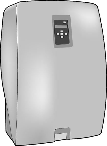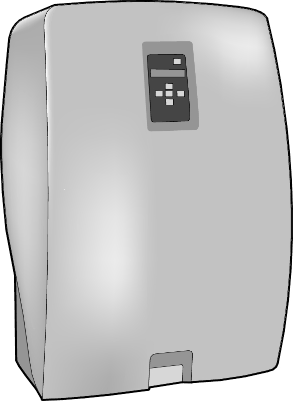
Vacuum deaerator for heating and cooling systems. With a pump and automatics for operation pressure and a control unit for automatic function and gas indication.
| Dimension range | 4,5 bar - 10 bar |
|---|---|
| PN | 10/16 |
| Temperature range | 0 °C to 90 °C |
| Material | Steel |
| Dimension range | PN | Temperature range | Material |
|---|---|---|---|
DN 15-20 | 10/16 | 0 °C to 90°C | Steel |

Releases loose gas from the fluid through pressure reduction to vaccum. For deaerating of heating and cooling systems with high static height and/or low system pressure. Applies especially to large and medium systems. The most effective way of venting closed heating and cooling systems.
Our vaccum dearetors are primarily intended for use where the fluid is water. Our larger models (S6A and S10A) can also be used in systems where the fluid is a mixture of water/glycol (max. 40%), if control and surveillance are expanded. Do not use salt/water mixtures.

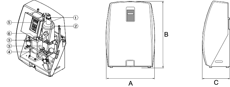
| Article | AT 8080S4A | AT 8080S4A-R | AT 8080S6A | AT 8080S6A-R | AT 8080S10A | AT 8080S10A-R | |||||
|---|---|---|---|---|---|---|---|---|---|---|---|
| A | 340 | 340 | 590 | 590 | 744 | 744 | |||||
| B | 490 | 490 | 880 | 880 | 1272 | 1272 | |||||
| C | 340 | 340 | 350 | 350 | 400 | 400 | |||||
| Connection | G 1/2 x 2pcs | G 1/2 x 2pcs | G 3/4 x 2pcs | G 3/4 x 2pcs | G 3/4 x 2pcs | G 3/4 x 2pcs | |||||
| Weight | 15 | 16 | 57 | 59 | 77 | 79 | |||||
| Dimensions in mm, weight in kg | |||||||||||

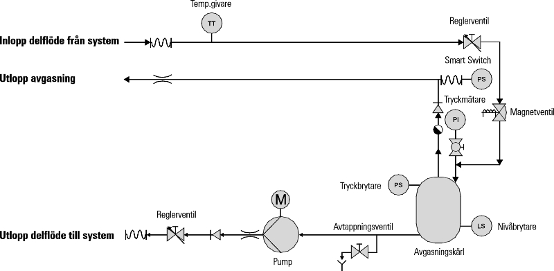
Fully automatic vaccum deaerator for liquid-filled heating or cooling systems. The liquid always contains both dissolved and unresolved gases. The unit's function is to reduce these gases to an absolute minimum. A separate subflow from the system is subjected to a vacuum in the unit's deaerating vessel. In this situation the dissolved gas is released and can be diverted to the atmosphere via the air deflector. This method provides a highly efficient deaerating in both heating and cooling systems, even in high buildings and/or low temperatures. The deaerator should always be mounted in the pipe's main line to get a 100% successful result on the liquid exchange.
A subflow is taken from the system and pumped into the deaerating vessel. The solenoid valve, which is in the inlet line, closes within a few seconds. The pump, that still is in operation, creates a vacuum. Acc. to Henry's law (the liquids natural solution of gas depends on pressure and temperature), the dissolved gas will be released and separated from the liquid and acts as free gas bubbles in the top of the deaerator chamber. In the next phase, the solenoid valve opens again, the pressure rises and a new part flows into the exhaust gas vessel. The new flowing subset presses the free gas blowers into the air deflector, on top of the deaerating chamber and leads them to the atmosphere via the float.
This shifting between having the solenoid valve open or closed causes the deaerating process to continue and the system's fluid becomes increasingly free of dissolved gases. In a period of time, usually 2-3 weeks, the amount of dissolved gas has decreased to a minimum. That´s when the built-in SmartSwitch-component stops the deaerating process if it does not detect any gas in ten minutes. The built-in clock does, if neccessary, activate the deaerating process at a certain preset time, usually 8:00 in the morning. However, if no gas is detected, the unit returns to standby mode, ready to restart 24 hours later. This smart feature minimizes the energy demand and increases the product's life.
All models have the features presented above. The R-models also have an integrated auto-filling equipment. This is controlled by preset start- and stop pressures. It can also be controlled by signals from e.g. level indication on an expansion vessel. Maximum filling amount, filling time and number of fillings can be limited.
| Article | AT 8080S4A | AT 8080S4A-R | AT 8080S6A | AT 8080S6A-R | AT 8080S10A | AT 8080S10A-R |
|---|---|---|---|---|---|---|
| Operating pressure (bar) within | 1,0 – 4,5 | 1,0 – 4,5 | 1,0 – 6,0 | 1,0 – 6,0 | 5,0 – 10,0 | 5,0 – 10,0 |
| Systemvol. max (m3) | 25 | 25 | 300 | 300 | 300 | 300 |
| Systemtemp. (°C) | 0 – 90 | 0 – 90 | 0 – 90 | 0 – 90 | 0 – 90 | 0 – 90 |
| Max. operating pressure (bar) | 10,0 | 10,0 | 10,0 | 10,0 | 16,0 | 16,0 |
| Treated fluid (l/h) | 70 | 70 | 1000 | 1000 | 1000 | 1000 |
| Filling amount(l/h) | - | 50 | - | 450 | - | 500 |
| Noise level (dB(A)) | 52 | 52 | 57 | 57 | 57 | 57 |
| Voltage (V) | 1-phase 230 | 1-phase 230 | 1-phase 230 | 1-phase 230 | 3-fas 400 | 3-fas 400 |
| Effect (W) | 100 | 100 | 800 | 800 | 1150 | 1150 |
| Enclosure class (IP) | 40 | 40 | 40 | 40 | 40 | 40 |
Carefully study the manual, especially the parts about operating, status reports and error messages. Attempt to fix the malfunction by studying the troubleshooting table. If the error persists, contact Armatec.
If you are about to disconnect the pressure deaerator, first make sure that the main power switch is turned off. Close the shut-off valve in the inlet- resp. the outlet line and an eventual filler valve. Then the deaerator can be dismantled. Be careful with any water remaining in the deareating vessel.
| AT-nr | Max. systemvolume | Operating pressure | Refill |
|---|---|---|---|
| 8080S4A | 25 m3 | 1,0 – 4,5 bar | No |
| 8080S4A-R | 25 m3 | 1,0 – 4,5 bar | Yes |
| 8080S6A | 300 m3 | 1,0 – 6,0 bar | No |
| 8080S6A-R | 300 m3 | 1,0 – 6,0 bar | Yes |
| 8080S10A | 300 m3 | 5,0 – 10,0 bar | No |
| 8080S10A-R | 300 m³ | 5,0 – 10,0 bar | Yes |