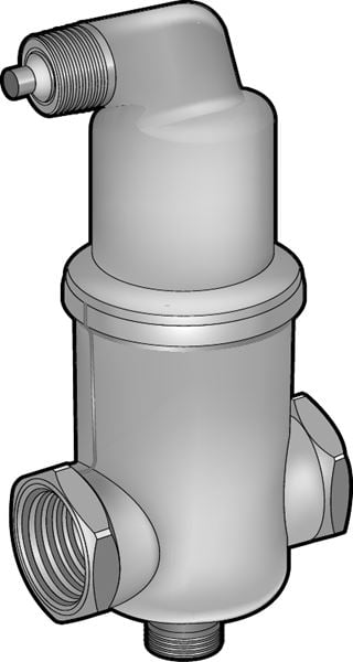
Automatic air deflector with dirt protection.
| Dimension range | G 3/4 - G 2 |
|---|---|
| PN | 10 |
| Temperature range | 0° C to 110 °C |
| Material | Brass |
| Dimension range | PN | Temperature range | Material |
|---|---|---|---|
G ¾ - G 2 | 10 | 0 °C to 110 °C | Brass |

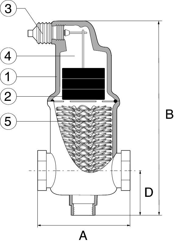
| 1 | Body and top of brass |
| 2 | Float of polypropylen, suspended in a bar |
| 3 | Unique valve mechanism in leak proof performance |
| 4 | Air chamber with large volume for max. operation safety |
| 5 | Gasseparator helistill optimally separates the free gas bubbles, |
| including microbubbles from the fluid |
| Connection | G 3/4 | G 1 | G 1 1/4 | G 1 1/2 | G 2 | ||||||
|---|---|---|---|---|---|---|---|---|---|---|---|
| A | 85 | 88 | 88 | 88 | 132 | ||||||
| B | 153 | 180 | 200 | 234 | 275 | ||||||
| D | 20 | 35 | 40 | 42 | 58 | ||||||
| Weight | 1,0 | 1,3 | 1,4 | 1,6 | 3,9 | ||||||
| Dimensions in mm. Weight in kg. | |||||||||||
The velocity descreases as the fluid flows into the separation body and the gas-free bubbles are being optimally separated when they pass through the separator. The separated bubbles flows up into the the float body. The liquid level goes down and the float sinks.
The float, that is connected with the separation mechanism by a chain, has reached a certain low level, the mechanism is affected and air can flow into the free. When the float rises again, the mechanism closes. The large volume of the air chamber and special design makes the liquid level never reach the drainage mechanism, even if the air in the chamber is compressed to 10 bar.
| Connection | 20 | 25 | 32 | 40 | 50 | ||||||
|---|---|---|---|---|---|---|---|---|---|---|---|
| Max flow I/sec | 0,35 | 0,55 | 1,0 | 1,4 | 2,1 | ||||||
| Max flow m3/h | 1,3 | 2,0 | 3,6 | 5,0 | 7,5 | ||||||
| Pressure drop bar | 0,017 | 0,013 | 0,014 | 0,014 | 0,02 | ||||||
| Values above apply at max. speed 1 meter/second. | |||||||||||
Since the micro bubbles are released at the hottest point in the plant, the component should be placed on the hottest spoint in the system. In a heating system is the warmest point usually on the supply line, as close to the heater as possible. In order to maintain a good absorption effect, the static pressure at the site of installation should not exceed 15-20mvc.
In a cooling system is the warmest point often in the return line before the cooler. To enable the float to move and blow out the air the pressure needs to ba around 0,3-0,5 bar by the installation point.
| Example: AT 8072B20 | |
| Connection | AT-No. |
|---|---|
| G 3/4 | 8072B20 |
| G 1 | 8072B25 |
| G 1 1/4 | 8072B32 |
| G 1 1/2 | 8072B40 |
| G 2 | 8072B50 |