| Dimension range | PN | Temperature range | Material |
|---|---|---|---|
DN 20-40 | 16 | max +90ºC | Brass |

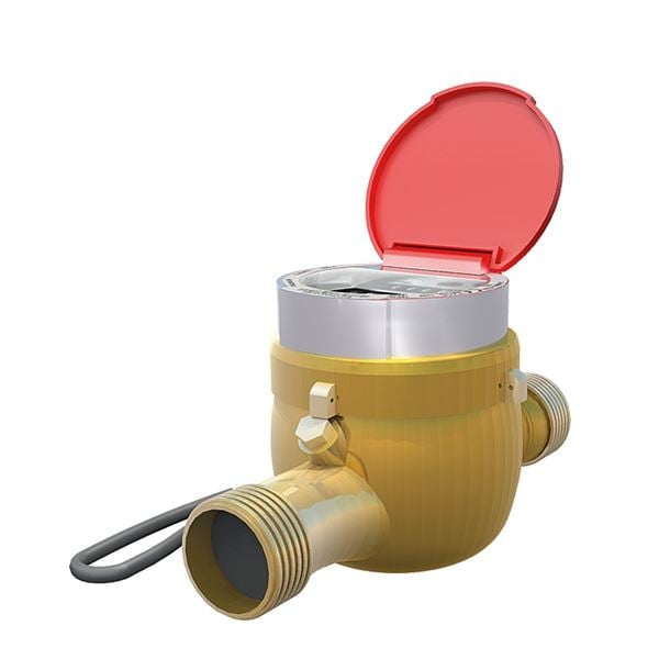
UGE.35 Flow meter, pipe mounted with a digital display, accumulated value
multi-jet residential water meter, AT 7029A with M-Bus interface EN 13757-2. Q3 .... m³/h, DN ...., threaded, PN 16.
| 1 | Body | Brass |
| 2 | Sealing material | EPDM |
| 3 | Vane | Polyether sulfone |
| 4 | Storage | Carbide/sapphire |

| Threaded Connection | ||||||
| Connection DN | 20 | 25 | 40 | |||
|---|---|---|---|---|---|---|
| Q3 | 4 | 10 | 16 | |||
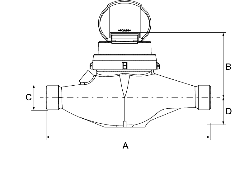
| A | 190 | 260 | 300 | |||
| B | 125 | 128 | 129 | |||
| C (Connection meter) | 1" | 11/4 " | 2" | |||
| D | 40 | 44 | 46 | |||
| Weight | 2,1 | 2,6 | 5,4 | |||
| Dimensions in mm, weight in kg. | ||||||

| Threaded Connection, standpipe or downcomer | ||||||
| Connection DN | 20 | 25 | 40 | |||
|---|---|---|---|---|---|---|
| Q3 | 4 | 10 | 16 | |||
| I | 105 | 150 | 200 | |||
| G | 148 | 169 | 226 | |||
| H | 130 | 143 | 190 | |||
| Weight | ||||||
| Standpipe | 1,9 | 3,0 | 6,0 | |||
| Downcomer | 2,0 | 3,4 | 7,3 | |||
| Measurements in mm, weight in kg. | ||||||
The flow sensor is a multi-jet residential meter. The vane is the only moving part in the media.
The calculator is according to GWF-codes and the calculator has a minimum rating of 1 liter with accuracy class R80.
7029A has built-in M-Bus modul(EN 13757-2) and M-Bus(EN 13757-3. The housing is protected from corrosion and mechanical wear. The display is equipped with an indicator pulley for optical readout in the test bench. The connection cable has a length of 1.5m.

| Ansl. DN | 20 | 25 | 40 |
|---|---|---|---|
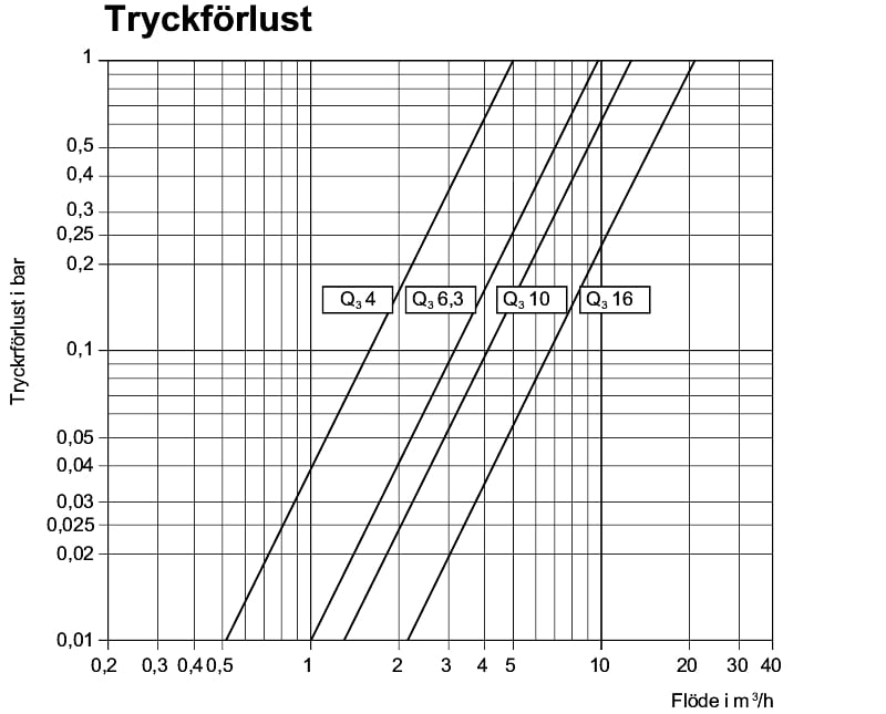
| Nominal flow Q3, m³/h | 4 | 10 | 16 |
| Overload flow, Q4, m³/h | 5 | 12,5 | 20 |
| Flow limit, Q2, liter/h | 80 | 200 | 320 |
| Minimum flow, Q1, liter/h | 50 | 125 | 200 |
| Minimum rating, liter | 1 | 1 | 1 |
| Numeric wheel | 8 | 8 | 8 |

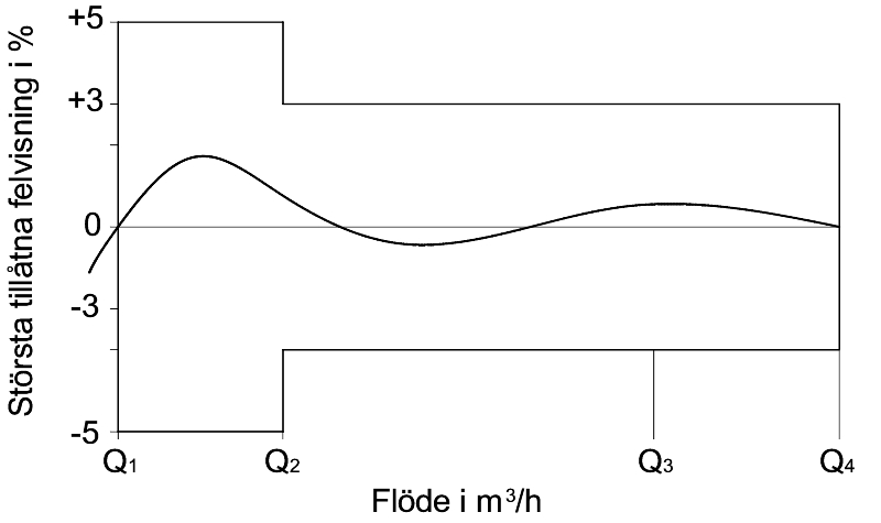
| Maximum allowed error | ||
| Flow range: | Q1-Q2 | +-5% |
| Q2-Q4 | +-3% |
The flow sensor must be mounted with the digit plate upwards. In standard version the meter should be mounted in a horizontal pipeline. Standpipe and downcomer design (Supplement S and F) shall be mounted in a vertical pipeline. Pay attention to the flow direction, an arrow on the meter body indicates the direction.
The meter is red with a red plastic lid. The meter is marked with make, Q3-value for resp. size and with the maximum temperature. The manufacturing number is indicated by 8 digits.
Example: AT 7029AG25-10M | ||||
|---|---|---|---|---|
| AT 7029A | G | 25 | -10 | M |
| Fig.no. | Performance | DN | Q3 | Built-in M-Bus output |
| G=Threaded (standard) | 20 | 4* | ||
| 25 | 10 | |||
| 40 | 16* | |||
| GS=Threaded Rising pipe *) | ||||
| GF=Threaded falling pipe *) | 25 | 6,3* | ||
| RSK-No. see RSK-register. |