Main facts
| Dimension range | PN | Temperature range | Material |
|---|
G 3/4-G 2 | 16 | +10 ºC to +130 ºC, short term 150 ºC | Brass |
| DN 20-40 | | | |
Range of application
For volume measuring of heating and cooling carriers with registration of consumed amount. Suitable as a flow sensor for energy measuring (in combination with integrator AT 7274 and temperature sensor pair AT 7276).
Program text
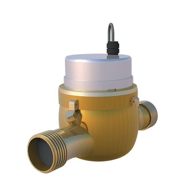
UGE.35 Meter for flow, pipe mounted with digital display, accumulated value
Flow sensor with energy measuring AT 7029 with built in pulse sensor qn/h, DN ....., flanged or threaded, PN 16, 1 pulse/ .... liter.
Quality Assurance
Performance according to SWEDAC STAFS 2006:4.
EG-type approval in class B. PTB-approval no 22.16/95.07.
Detail specification
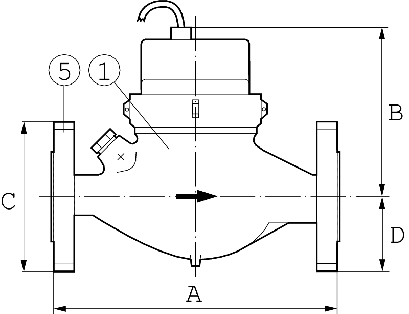
| 1 | Body | brass | stove enamelled |
| 2 | Insert | polyphenylene sulfide | |
| 3 | Vane wheel | polyethersulfone | |
| 4 | Layer | hard metal/sapphire | |
| 5 | Flanges | steel | stove enamelled |
Dimensions and weight
| Fanged connection | | | |
| Connection DN | 20 | 25 | 40 |
|---|
| qp | 2,5 | 6 | 10 |
|---|
| A | 190 | 260 | 300 |
| B | 111 | 128 | 129 |
| C | 105 | 115 | 150 |
| D | 46 | 51 | 68 |
| E | 95 | 101 | 131 |
| Weight | 3,5 | 4,8 | 8,0 |
| Measurements in mm, weight in kg. | | | |
Threaded connection (modell G)
| Threaded connection | | | | |
| Connection DN | 20 | 20 | 25 | 40 |
|---|
| qp | 1,5 | 2,5 | 6 | 10 |
|---|
| A | 190 | 190 | 260 | 300 |
| B | 118 | 118 | 124 | 127 |
| D | 36 | 36 | 46 | 63 |
| E | 97 | 97 | 103 | 140 |
| Vikt | 2,0 | 2,1 | 2,9 | 5,2 |
| Measurements in mm, weight in kg. | | | | |
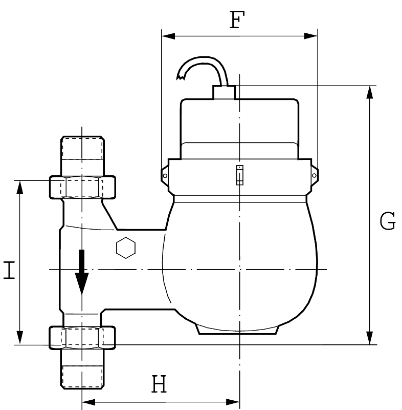
Threaded connection, standpipe (modell GS) and downpipe performance (modell GF)
| Threaded connection, standpipe and downpipe performance | | | | |
| Connection DN | 20 | 20 | 25 | 40 |
|---|
| qp | 1,5 | 2,5 | 6 | 10 |
|---|
| F | 97 | 97 | 103 | 140 |
| G | 155 | 155 | 170 | 190 |
| H | 82 | 82 | 94 | 120 |
| I | 105 | 105 | 150 | 200 |
| Weight | 2,0 | 2,1 | 3,3 | 5,0 |
| Measurements in mm, weight in kg. | | | | |
Function and design
The flow sensor is of dry running, multibeam vane wheel type. The vane wheel is the only movable part in the media, the down shift is done completely dry running. The counter is a rolling counter. The counter is a minimum grade of 1 liter. The entire m3 is shownwith white numbers and the liters in red.
The pulse sensing is done with a built in pulse sensor of the type Reed switch. The pulse number can be ordered as 1, 2, 5, 10 (standard) or 25 liter/pulse. The pulse sensor is magnetically shielded and delivered with a 2 meter connection cable. The meter body is internally and externally stove enamelled. and through that protected against corrosion and mechanical wear. The dial is provided with an indicator trot for optical reading in test bench.
Technical data
| Connection DN | 20 | 20 | 25 | 40 |
|---|
| Nominal flow qp, m³/h | 1,5 | 2,5 | 6,0 | 10 |
| Allowed continuous load, max , m³/h | 1,5 | 2,5 | 6,0 | 10 |
| Short term overload, qs, m³/h | 3 | 5 | 12 | 20 |
| Minimum flow, qi liter/h | 30 | 50 | 120 | 200 |
| Pressure loss by qp, bar | 0,11 | 0,18 | 0,25 | 0,25 |
| Flow by pressure loss 1 bar, m³/h | 4,7 | 6,0 | 12,5 | 20,5 |
| Minimum grade, liter | 1 | 1 | 1 | 1 |
| Number of numeric pulleys | 8 | 8 | 8 | 8 |
Pulse sensor
| Specification pulse sensor | |
|---|
| Pulse sensor | Type Reed switch, fixed mounting |
| Max breaking current | 0,1 A |
| Max voltage | 28 V |
| Max transfer resistance | 105 Ohm |
| Cable length | 2 m |
Sizing
The smallest meter that can handle the given flow is selected. Do not over dimension, during a borderline case, choose the smaller of the two options. Control that the pressure loss doesn't become to big. "Short term overload" is considered to be less than an hour per day or at most 200 hours per year.
Accessories and variants
AT 7029 is available with both flanges and a variant with threaded connections (add G to the end of the article number) for mounting in console in standard building height. The meter has threaded connections and also available in standpipe and downpipe performance (add GS or GF respectively in the article number see how to order). The pulse number can be ordered as 1 liter, 2,5 liters, 10 liters (standard) or 25 liters per pulse.
Installation
The flow sensor should be mounted with the dial upwards. In standard performance the meter should be mounted in a horizontal pipe line. Standpipe and downpipe performance (add S or F respectively) should be mounted on a vertical pipe line. For energy measuring the meter is mounted on the lower temperature, i.e. the return pipe for heating facilities and the inlet pipe for recycling and cooling facilities. A straight pipe before this meter is not required. On the other hand a filter should be mounted up stream from the meter. The system should be clean flushed before mounting. During comissioning pressure surges in the system should be avoided.
Maintenance and spare parts
The flow sensor is according to Boverket's regulations subject to recurring control (meter revision) with an interval of 5 years, where the accredited control body will revise and control the meter. During this revision the worn out pieced will be replaced. Spare parts for this are available in separate spare parts section.
Marking
The meter is red with a gray plastic lid. The meter dial is marked with manufacturer, qn-value for meter size and max temperature respecively.
How to order
| Example: AT 7029G25-6P10 | | | | |
| AT 7029 | G | 25 | -6 | P10 |
|---|
| Article number | Performance | DN | qp | Liter/pulse |
| -= Flanged performance | 20 | 1,5 | 1 |
| G= threaded performance (standard) | | 2,5 | 10 (standard) |
| GS= threaded standpipe performance | 25 | 6 | 25 |
| GF=Threaded down pipe performance | 40 | 10 | |
| For RSK-number see RSK-register. | | | | |


