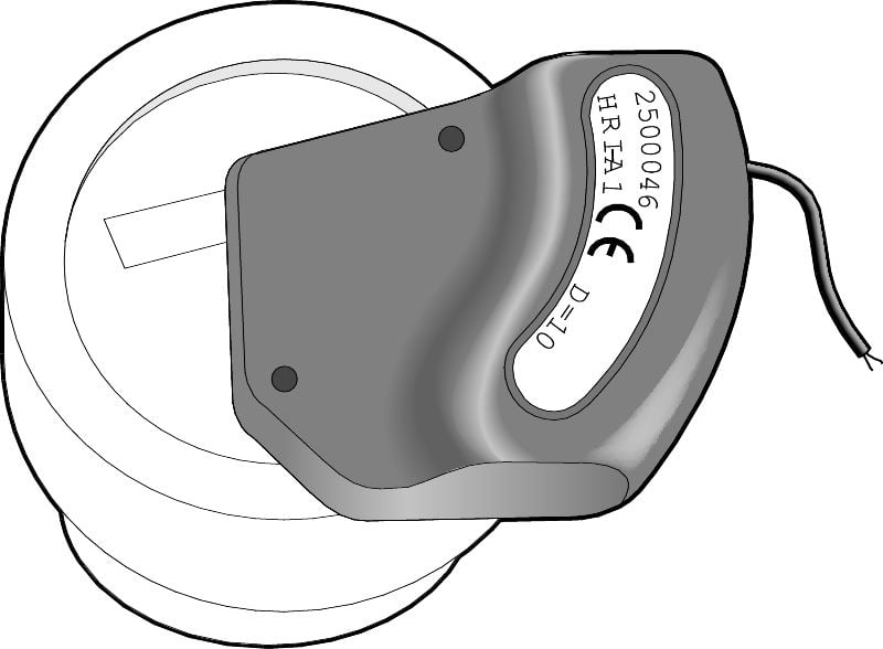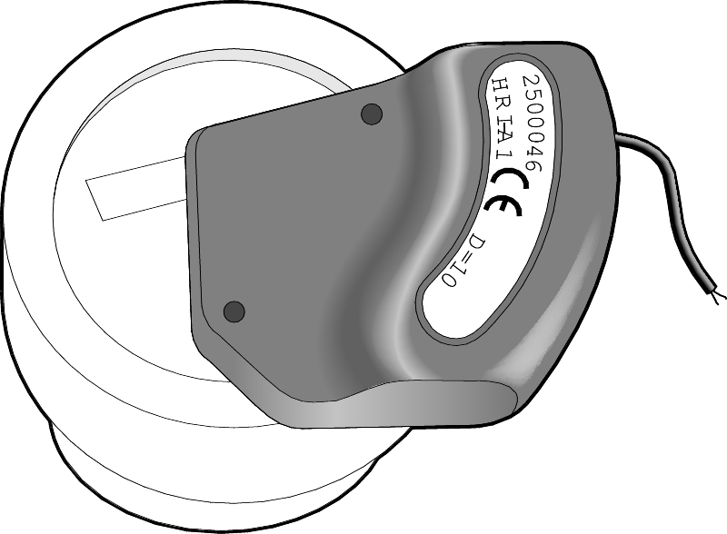

HRI is an inductive universal sensor for remote reading/transfer of measurement values via M-bus, pulse or radio RF from water meter to data center or measurement systems. The sensor is compatible with Armatecs piston measuring chamber design type AT 7420, 7430, 7050. The unit is mounted on top of the meter's display board.
HRI is available in 3 versions:
CE-marking
The product is manufactured according to the requirements for electromagnetic compatibility in accordance with EEC Directive 98/34, European Standard EN61000-6-1.
The HRI device inductively reads the number of rotations on the metal indicator, located under the glass on the water meter's display board. The relation between the number of rotations and the read pointer is equal to D. D = number of liters per pulse and exists in different pulse numbers, eg 1, 10 and 100.
The HRI-unit has a built-in lithium battery for more than 10 years of operation. Measurement value and settings are maintained in case of power failure (e.g interference on the M-Bus loop). In case of power failure, the data-bus (M-bus/Mini-bus) will continue to register the values.
| Cable lenght: | 1,5m (does not apply to radio detectors) |
| Protection: | IP 68 (Hermetically sealed) |
| Storage temperature: | -20 °C to +65 °C |
| Ambient temperature: | -10 °C to +65 °C |
| Battery: | Lithium. Lifetime 10 +1 years (stockholding) |
| Data interface | |
| Type: | M-bus och Mini-bus |
| Speed: | Automatic recognition, 300/2400 Baud |
| Protocol: | Acoording to IEC 870 / EN 1434-3 |
| Data: | Measurement and measurement number (12 numbers as standard) |
| Max Cable lenght: | According to M-bus specifications |
| Pulse output (I1, I2) enl. ISO/TC 30/SC 7/ WG 8 | ||
| Pulse type: | Open Collector, transistor relay (potential dependent)* | |
| Input voltage: | max 24 V | |
| Input current: | max 20 mA | |
| Input power: | max 0,48 VA | |
| Inner resistance: | 100 Ohm | |
| Max. output frequency: | 5 Hz; 124 ms pulse width | |
| Memory/storage: | up to 1 000 000 reversed pulses | |
| *To get a potential-free pulse, the AT 7281-2PCD must be mounted after the pulse sensor | ||
Cable coupling, AT 7299IP68KAB:
As an accessory, there is a cable connection with protection class IP68 when you need to wire the cable to e.g a water-filled well.
HRI Pulse encoder
- The output pulse (on the sensor indicated D..) is available with pulse rate: 1, 10, 100, 1000 liters per pulse. The pulse rate is permanently programmed from the factory. Sensors with pulse rate 10 are most common.
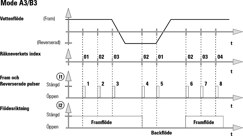
- Depending on the application, the HRI pulse encoder can be obtained in different models, but usually A4 is used. The function is illustrated in the following diagram.

HRI Data sensor
The data editor has an interface for reading measurement data and subsequent configuration. It also acts as an encoder with the ability to reprogramm the pulse count and the meter reading. Programming is done using PC-based service software MiniCom, via the M-bus loop and level converter, for example. AT 7530MR003USB.
Programmable settings are:
M-bus displays in standard version metrics with 8 digits with color display.
The meter has to be prepared for HRI and an indicator equipped with a metal plate.
Before mounting the sensor, the transport foil on the underside of the sensor has to be removed.
Assembly of the HRI-unit is done without the need to break any seals on the sensor, and this can be done either directly when the meter is mounted or afterwards when the meter already has been mounted.
The HRI-unit is screwed into place on the glass of the visor-glass in prepared attachment points with the supplied screws. Alternatively, the supplied attachment is used for sensor counter with copper/glass enclousre.
Adapted protective cover to the meter's display board is included for replacement.
The pulse encoder connection cable can be extended up to 50m, whereas the data wiring cable can be extended in accordance with the M-bus standard. Transient volt protection is recommended for outdoor wiring.
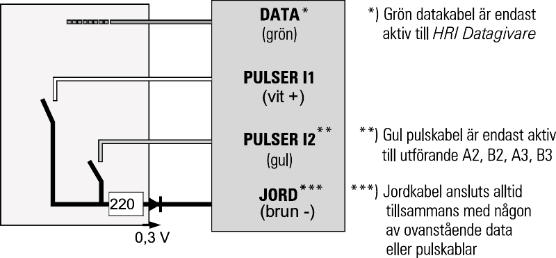
The HRI-unit is supplied with a four-wire connection cable as follows: M-bus, green and brown cable. Pulse, White (+) and brown (-) cable.

| Cable | Type of HRI pulse output (A..) / Data sensor (B..) | |||||
|---|---|---|---|---|---|---|
| A4/B4 (standard) | A2/B2 | A3/B3 | ||||
| DATA (green) | M-bus* and Mini-bus | M-bus* and Mini-bus | M-bus* and Mini-bus | |||
| l1 (white) | Balanced pulses** | Forward flow pulses | Forward-/backflow pulses | |||
| l2 (yellow) | Manipulation/Error | Backflow pulses | Flow direction | |||
| *) External power supply can be supplied via the DATA cable: recommended 24 V DC (abs. max 50 V DC). | ||||||
| **) Balanced pulses: Backflows must be compensated by identical forward flow before more pulses are taken out. This means that no output pulses are output during this period, even if the sensor counts forward. | ||||||
The HRI-sensor is always labeled with the manufacturer's number, which for the data tuner corresponds to the secondary print. The data tuner is labeled with B4 by default. The encoder is by default marked with A4-D ...., where the number after D indicates the pulse weight in liters per pulse.
| Exampel: AT 7275HRI-A4-D10 | ||
| AT 7275HRI | -A4 | -D10 |
|---|---|---|
Fig. no. | Sensor type | D=Pulse number (liter/pulse) |
| A4=Pulse encoder | 1 / 10 / 100 /1000 liters per pulse. | |
B4-D1=Datagivare (M-bus/Mini-bus, as well as programmable pulse) | (The data sensor is set to 1 lite rper pulse by default, D1) |