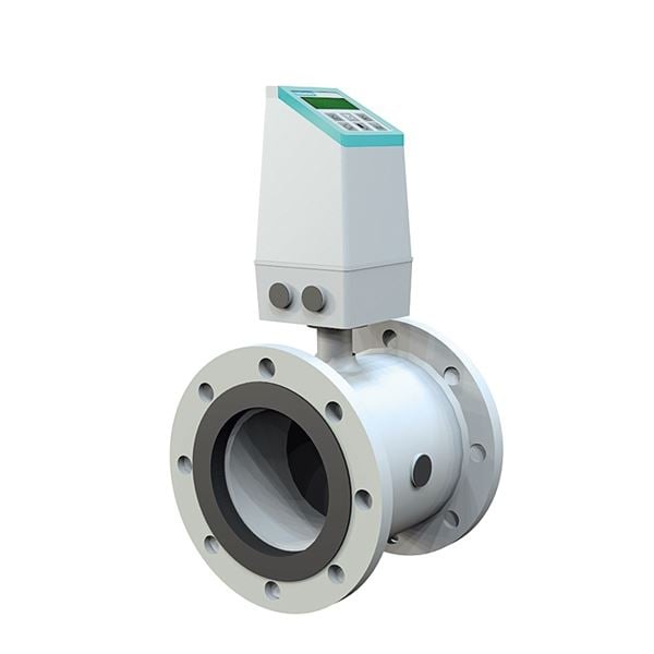
Flow range with inductive metering principle for measuring flows on conductive fluids in closed pipe systems. Suitable for most media like cold water and warm water, sewage water mm. Used for process control and distribution facilities. Can be used for thermal energy measurement.
| Dimension range | DN 15 to DN 1200 |
|---|---|
| PN | 10 to 16 |
| Temperature range | -10ºC to +70ºC, short term +90ºC (as an option -20ºC to 130ºC PTFE lining) |
| Material | NBR alternatively.EPDM |
| Article number | Amount |
|---|---|
| AT 7185- | |
| AT 7185-E | |
| AT 7185-P | |
| AT 7185-MAG5 | |
| AT 7185-MAG6 | |
| AT 7185WALL | |
| AT 7185SUB | |
| AT 7185-10C | |
| AT 7185-10SC |
| Dimension range | PN | Temperature range | Material |
|---|---|---|---|
DN 15-1200 | 16/10 | -10°C to 70 ºC (short term 90 ºC) | Carbon steel, Lining: NBR alt. EPDM |
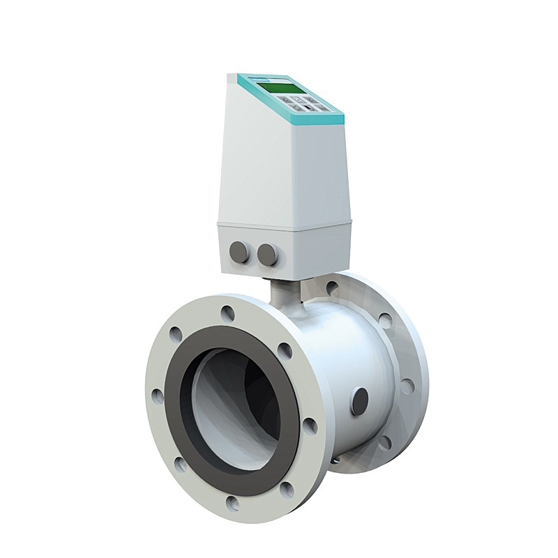
UGE.35 Meter for flow, pipe mounted with digital display accumulated value
Flow meter, magnetically inductive, AT 7185, DN ..... PN... Internal lining of..... Signal converter compact (alternatively wall mounted) type AT 7185 alt. MAG6.
| 1 | Body and flanges | Carbon steel ST 37.2, two-component epoxy coating (Corrosivity category C4) |
| 2 | Lining | NBR hard rubber (standard) alt. EPDM |
| 3 | Electrodes | Hastelloy C276 |
| 4 | Signal converter | Fiberglass reinforced polyamide |
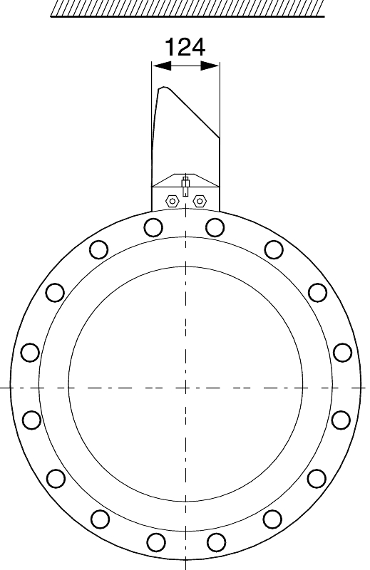
| EN 1092-1 PN 16 | Excluding signal converter | Including signal converter | ||||||
|---|---|---|---|---|---|---|---|---|
| DN | A *) | B | C | Vikt **) | ||||
| 50 | 200 | 188 | 341 | 9 | ||||
| 65 | 200 | 194 | 347 | 11 | ||||
| 80 | 200 | 200 | 353 | 12 | ||||
| 100 | 250 | 207 | 360 | 15 | ||||
| 125 | 250 | 217 | 370 | 20 | ||||
| 150 | 300 | 232 | 385 | 26 | ||||
| 200 | 350 | 257 | 410 | 48 | ||||
| 250 | 450 | 284 | 437 | 69 | ||||
| 300 | 500 | 310 | 463 | 86 | ||||
| 350 | 550 | 382 | 535 | 115 | ||||
| 400 | 600 | 407 | 560 | 125 | ||||
| 500 | 600 | 463 | 616 | 189 | ||||
| 600 | 600 | 514 | 667 | 301 | ||||
| 700 | 700 | 564 | 717 | 320 | ||||
| 800 | 800 | 616 | 769 | 428 | ||||
| 900 | 900 | 663 | 816 | 619 | ||||
| 1000 | 1000 | 714 | 867 | 636 | ||||
| 1200 | 1200 | 820 | 973 | 813 | ||||
| Dimensions in mm, weight in kg | ||||||||
| All flange dimensions according to EN 1092-1 (or ANSI B 16.5 on request) | ||||||||
| *) If grounding flanges are mounted as an option, these and the strainer need to be added to the height. | ||||||||
| **) With mounted signal converter MAG6000/5000 increases the weight with roughly 1 kg. | ||||||||
The meter principle based on Faraday's induction law that says that when a conductor(fluid) moves through a magnetic field(meter pipe) it creates an induced current. This current is directly proportional to the flow. The meter readings is handled by the signal converter which gives the desired output signal. A prerequisite is that the conductive ability of the fluid is over 5 mikroS/cm.
The flow meter consists of a meter pipe, completely without movable parts and a signal converter that is mounted directly on the meter pipe or separately on a wall. The meter pipe is provided with a lining to decrease the risk for internal build up. The lining is selected based on the area of use, temperature etc. grounding electrodes are integrated in the meter pipe.
Signal converter MAG 5000
Wide meter area with high accuracy (± 0,4% of measured value). LCD-indicator for reading. Doesn't need calibration. Equipped with self diagnosis, automatic zero point adjustment and indicated an empty meter pipe and flow direction signal. Is available with type approval for cold water.
Signal converter MAG 6000
Very high accuracy (±0,2% of measured value). Dosing function. Limit alarm. In other aspects similar to MAG 5000.
| Meter pipe MAG 5100W | |
| Flow range | See connection in table |
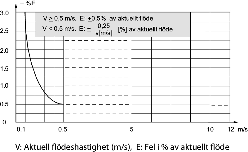
| Meter accuracy | ±0,5 %, see chart |
| Pressure loss at 3 m/sec. | DN 50-300 (down coned 1 DN): max. 25 mbar |
| DN 350-1200: as straight pipe | |
| Lowest conduction ability of media | 5 mikroS/cm |
| Protection class | IP 67 enl. EN 60529, 1 mvp under 30 min. |
| Flanges | According to EN 1092-1 (ANSI B16.5 as option) |
| Pressure and temperature | ||
| Pressure | DN15...DN40 | PN 40 |
| DN 50... DN 150 | PN 16 | |
| DN 200... DN 1200 | PN 10 (DN 200..DN1200 option PN16) | |
| Media temperature | DN 15... DN 1200 | -10...70 °C |
| Signal converter | ||||
| Accuracy | MAG5000 | ±0,4% | ||
| MAG6000 | ±0,2% | |||
| Operational current | 115/230 V AC (alternatively 24 V AC/DC, 11...30 V) | |||
| Protection class | IP 67 according to IEC 529 and DIN 40050, 1 mvp under 30 min. | |||
| Surrounding temperature | During operation | -20 till +50°C | ||
| Storage | -40 till +70°C | |||
| Signal output | Analog | 0-20 mA eller 4-20 mA | ||
| Resistance | <800 ohm | |||
| Tidskonstant | 0,1-30 s. adjustable | |||
| Digital output | Frequency | 0-10 kHz 50% cycle | ||
| Time constant | 0,1-30 s. adjustable | |||
| Active | 24 V DC, 30 mA, 1 K Ω≤Rload≤ 10 K Ω | |||
| Passive | 3-30 V DC max. 110 mA, 200 Ω ≤Rload≤ 10 K Ω | |||
| Relay | Change-over relay | |||
| Current | 42 V AC/2 A, 24 V DC/1A | |||
| Digital input | 11-30 V DC, Ri=4,4 k Ω | |||
| activation time | 50 ms | |||
| Current | I11 V DC = 2,5 mA, I30 V DC = 7 mA | |||
| Functions | instantaneous and total flow, stop function by low flow or empty pipe, | |||
| Indication of flow direction, error messages, run time, limit switch, | ||||
| uni/bidirectional flow, pulse output, control of cleaning and dosing 1) | ||||
| Galvanically isolated | All in- and outputs are galvanically isolated | |||
| Stop function | Low flow | 0-9,9% of max flow | ||
| Empty pipe | Detection of empty meter pipe | |||
| Counter | Two eight figure counters for front, net and back flow | |||
| Display | LCD-display with back lighting with alpha numerical text, | |||
| 3 x 20 characters for indication of flow, total readings, settings and error messages | ||||
| Back flows are indicated with negative characters. | ||||
| Time constant | Time constant as actual output | |||
| Zero point adjustment | Automatic | |||
| Electrode input impedance | > 1 x 10¹⁴ Ω | |||
| Communication | Standard | Prepared for additional client mounted modules | ||
| 1) Only MAG 6000 | ||||
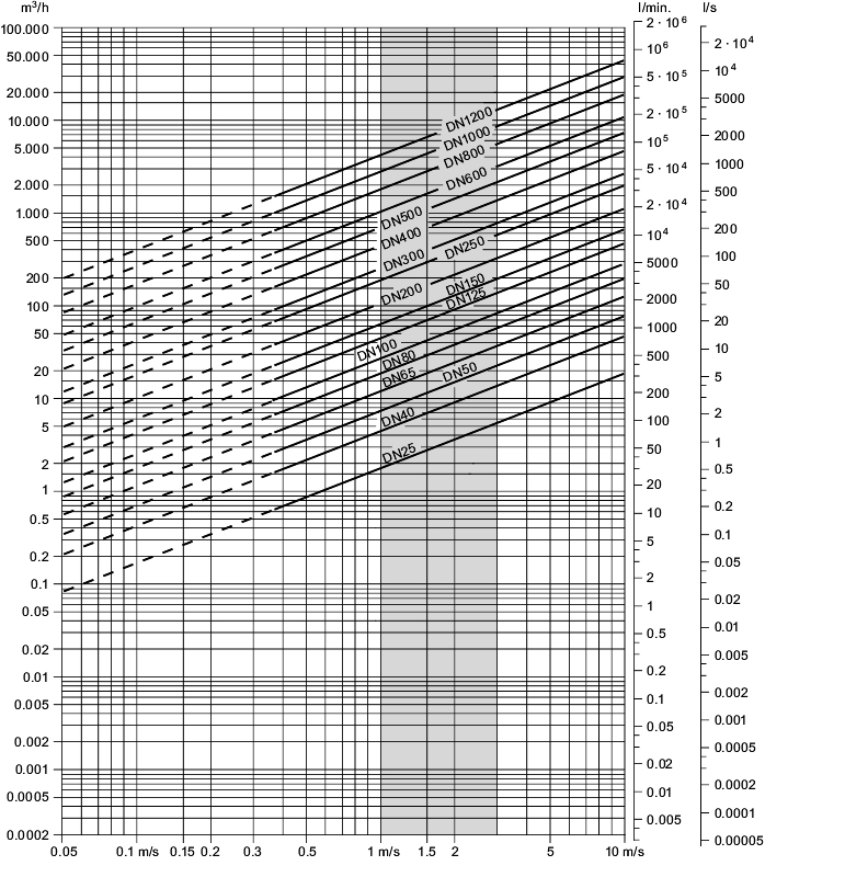
The graph below shows the relation between flow speed, V, flow quantity, Q and the flow meter dimension DN.
Selection of flow meter
For sizing pick approtiate meter that gives a flow speed withing 2...3 m/s or more is recommended. This is partly to secure a good gauging accuracy, but also to prevent build up on the electrodes and insulation lining in the meter pipe. This gives in general at least one dimension less on the meter than the pipe line. In that case control that the pressure loss in the down cone doesn't get to large.
For measuring fluids with a high particle content the flow speed should be within 3...5 m/s or more to prevent internal build up.
| Description | Artikelnr. | |
|---|---|---|
| Signal converter MAG 5000 | Wide range with high accuracy (±0,4 % of measured reading). | |
| LCD-indicator for reading. Does not need calibration. | ||
| Equipped with self diagnosis, automatic zero point adjustment and indicates empty meter pipe and flow direction signal. | AT 7185-MAG5 | |
| Signal converter MAG 6000 | Very high accuracy (±0,2 % of measured reading). | |
| Dosing function. Limit alarm. In other aspects similar to MAG 5000. | AT 7185-MAG6 | |
| Meter pipe lining | Alternate material, PTFE-teflon (temp. area-20...130 alt. 180 °C). | |
| Used for e.g. in Glycol- and larger heating systems. | se How to order | |
| Pressure class | Option PN 16 DN 200-1200 | se How to order |
| Capsule kit | Submersible performance (IP 68, 10 mvp in 10 years) for use with | |
| standard MAG 5000 signal converter, when the meter pipe is buried or submersed. | AT 7185SUB | |
| Grounding/protection flange | Type C. Extra grounding ring (e.g. DN 100) | AT 7185-100J |
| Wall mounting kit | To IP 67 version. Including wall mounts and 5 st. Pg13 screwed cable entries. | AT 7185WALL |
| Standard electrodes and signal cable | 3 x 1,5 mm2 PVC in the lengths: 10 m, 20 m, 40 m, 60 m and 100 m. (t.ex. 10 m.) | AT 7185-10C |
| Special electrodes and signal cable | Double screened PVC (recommended for long distances and when | |
| detection of empty pipe is used). | ||
| Available in the lengths: 10 m, 20 m, 40 m, 60 m and 100 m. (e.g. 10 m.) | AT 7185-10CS |
The flow meter can be installed so that the meter pipe is always filled with liquid, in horizontal mode or vertically. Avoid high points or dropping pipes.
Straight lines of at least 5xD before the meter and 3xD after is required. Eventual down coning can be used on the straight. Choose a position where the flow isn't pulsating and avoid places where the meter is exposed to electromagnetic interferance.
With media temperatures > 90oC compact mounting with signal converter on the meter pipe not possible. Use signal cable (e.g. AT 7185-10C) and wall mounting kit (AT 7185WALL).
In other cases, please see the separate instruktion manual.

| Meter pipe (NOTE! Signal converter are ordered separately, see next How to order) | |||
| Example: AT 7185-100P-PN16 | |||
| AT 7185 | -100 | P | -PN16 |
|---|---|---|---|
| Fig. nr. | DN | Lining (option) | Pressure class (option) |
| NBR hard rubber (standard) | PN 16 for DN 200-1200 |