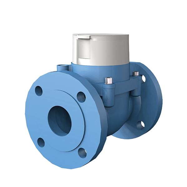
Cold water meter with turbine wheel, type Woltmann for distributions and pumping facilities with an accuracy of R100. Flanged connection with a large flow area and low pressure. Can be mounted both horizontally and vertically. Prepared to be equipped withy communication module type Cyble with pulse, M-Bus or wM-Bus.
| Dimension range | DN 50 to DN 150 |
|---|---|
| PN | 16 |
| Temperature range | +1ºC to +50ºC |
| Material | Cast iron |
| Article number | Amount |
|---|---|
| AT 7110B50-200 | |
| AT 7110B65-200 | |
| AT 7110B80-225 | |
| AT 7110B100-250 | |
| AT 7110B125-250 | |
| AT 7110B150-300 | |
| AT 7275CY-M2 | |
| AT 7275CY-KLF1 | |
| AT 725CY-KLF10 | |
| AT 7275CY-KLF100 |
| Dimension range | PN | Temperature range | Material |
|---|---|---|---|
DN 50 - 150 | 16 | +1 °C to 50 ºC | Cast iron |
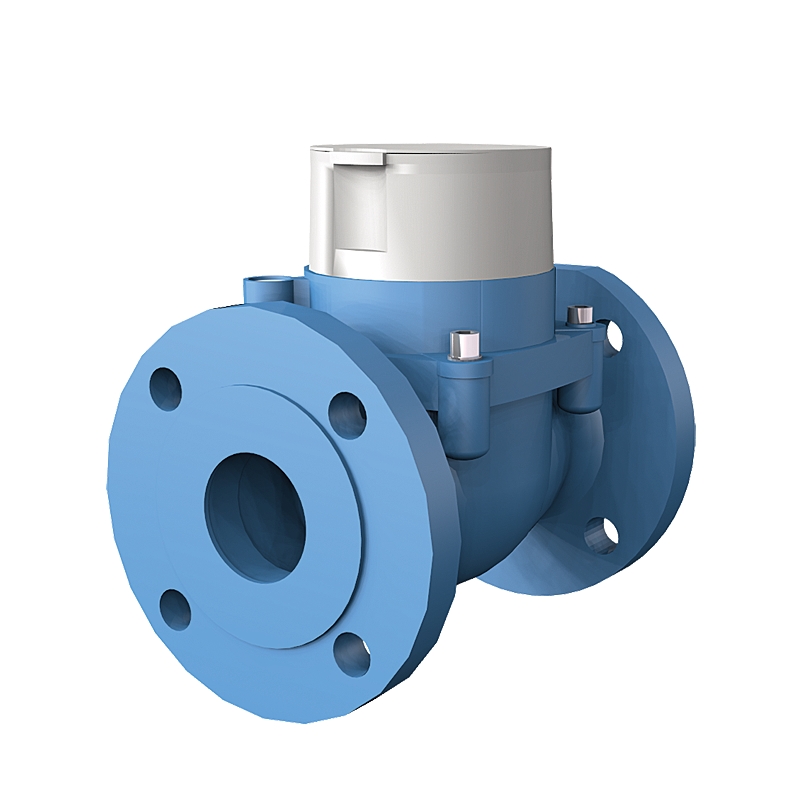
UGE.35 Water meter for flow, pipe mounted with digital display, accumulated value.
Cold water meter AT 7110B.... type Woltmann, prepared for remote reading module, Q3 .... m3/h, DN .... with flanges PN 16.
| Component | Material |
|---|---|
| Body | Cast iron |
| Meter chamber | PPO |
| Support pin | Hard metall |
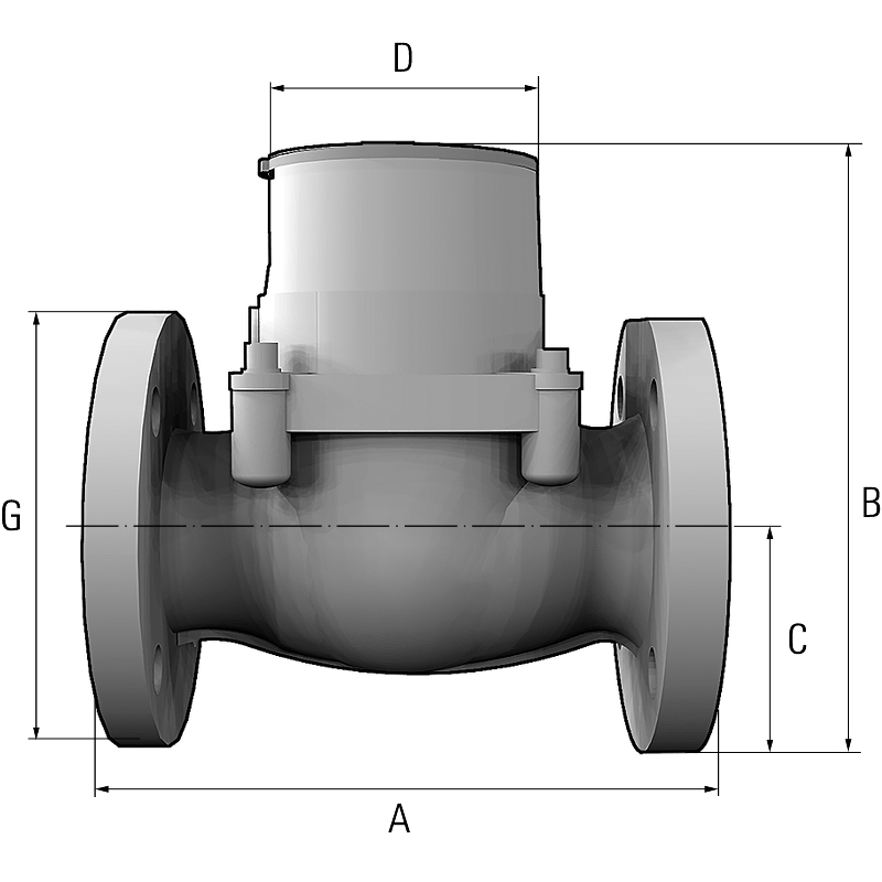
| DN | 50 | 65 | 80 | 100 | 125 | 150 | ||||||||||||
|---|---|---|---|---|---|---|---|---|---|---|---|---|---|---|---|---|---|---|
| A | 200 | 200 | 225 | 250 | 250 | 300 | ||||||||||||
| B | 224 | 234 | 242 | 279 | 279 | 339 | ||||||||||||
| C | 82,5 | 92,5 | 100 | 110 | 110 | 142,5 | ||||||||||||
| D | 80 | 80 | 80 | 80 | 80 | 80 | ||||||||||||
| Weight | 11,4 | 12,6 | 14,1 | 19,5 | 19,5 | 34 | ||||||||||||
| Measurements in mm, weight in kg. | ||||||||||||||||||
Cold water meter Woltex type turbine wheel, where a free floating spherical turbine unit rotates in the water current, which entails low friction.
The movement is transfered with a magnetic coupling to the counter.
The counter is eight figures, hermetically sealed and also rotatable in 360o, so the counter display can be turned into suitable position.
The meter is provided with an indicator for connection of remote reading module type Cyble, either M-Bus or Pulse. See separate product sheet AT 7275CY.
| DN | 50 | 65 | 80 | 100 | 125 | 150 | |||||||
|---|---|---|---|---|---|---|---|---|---|---|---|---|---|
| Q3 , permanent flow (m3/h) | 40 | 63 | 100 | 160 | 160 | 400 | |||||||
| Q1 , minimum flow, (m3/h) | 0,4 | 0,63 | 1,0 | 1,6 | 1,6 | 2,5 | |||||||
| Q2 Transitional flow, (m3/h) | 0,64 | 1,0 | 1,6 | 2,56 | 2,56 | 4,0 | |||||||
| Q4, Overload flow (m3/h) | 50 | 79 | 125 | 200 | 200 | 500 | |||||||
| Q3/Q1, Ratio (R-tal) standard | 100 | 100 | 100 | 100 | 100 | 100 | |||||||
| Start flow, (m3/h) | 0,19 | 0,22 | 0,25 | 0,38 | 0,38 | 0,4 | |||||||
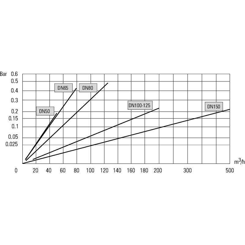
| Pressure loss by Q3 according to EN 14154, (bar) | 0,16 | 0,4 | 0,4 | 0,4 | 0,4 | 0,16 | |||||||
The values above (exclusive start and pressure loss) shows the meteorological properties according to the standard MID. | |||||||||||||
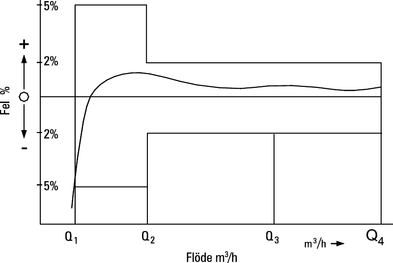
| Flow range | Largest allowed margin of error |
| Q1 - Q2 | ±5% |
| Q2 - Q4 | ±2% |
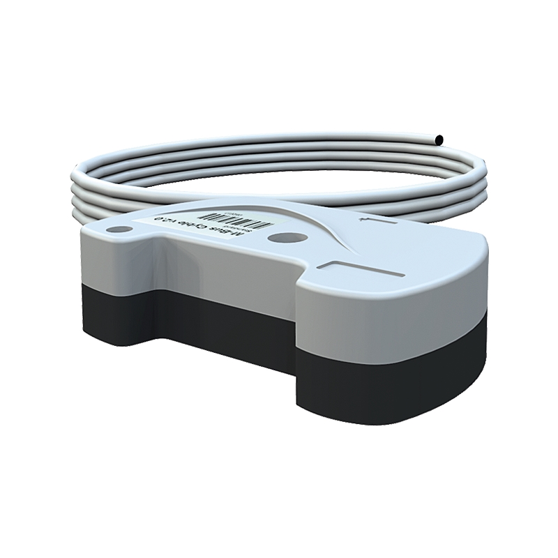
Accessories
Remote reading modules type M-Bus or Pulse. For more information on remote readings modules see separate product sheet AT 7275CY.
