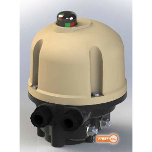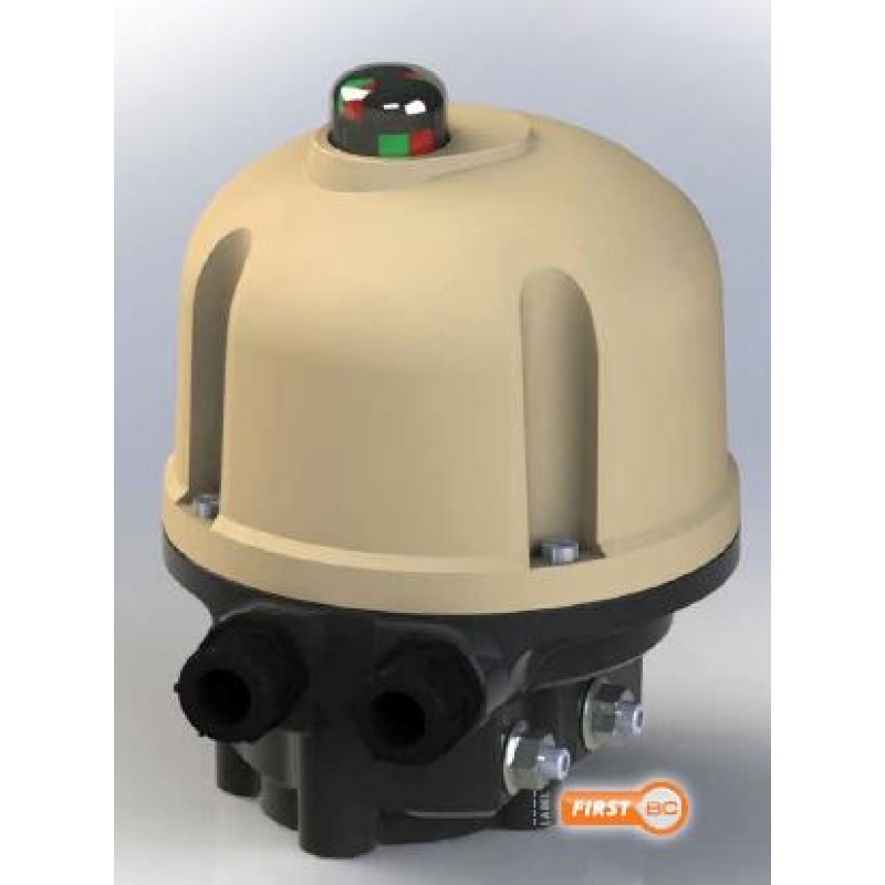
Electric actuator for on/off or control of ball valves, butterfly or where a 90° rotation is required.
| Torque | 15 Nm to 70 Nm |
|---|---|
| Driven | Electric 85-260 V 50-60Hz and 24VDC |
| Fits valves: | AT3502, AT3507, AT3533S, AT3534S, AT3542, AT3547, AT3582, AT3585, AT3590, AT2282, AT 2310-2319, AT2270B |
| Article number | Amount |
|---|---|
| AT 3940-1 | |
| AT 3940-1-POS | |
| AT 3940-3 | |
| AT 3940-3-POS | |
| AT 3940-7 | |
| AT 3940-7-POS |

Weather-proof actuator for on-off actuation or control of ball valves, butterfly or where a 90° rotation is required. Torque 15, 30 or 70 Nm.
UEC.11 Valve actuator, electric, two-position without spring return
Actuator Bernard Electrical AT 3940 for 90°. Maneuvering of ball-, butterfly- or where a 90° rotation is required.

CE-Marking
EC Directives 2004/108/EC, 2006/95/EC and fulfills the EN 61000-6-4, EN 61000-6-2, EN 60034-1 and EN 60529.
IP 68 rated.
| Detail | Material | Surface treatment | |
|---|---|---|---|
| 1 | Body | Aluminum | |
| 2 | Cope | Aluminum | Epoxy-painted RAL 1014, C3 acc. to ISO 12944 |
| 3 | Drive shaft | Solid steel | Untreated |
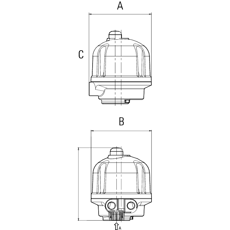
| Actuator/Fig. no | Standard drive shaft | A | B | C | Weight |
|---|---|---|---|---|---|
| 3940-1 | 14x14, 11x11, 9x9 | 150 | 145 | 175 | 2,5 |
| 3940-3 | 14x14, 11x11, 9x9 | 150 | 145 | 175 | 2,5 |
| 3940-7 | 22x22, 17x17, 14x14, 11x11 | 150 | 145 | 175 | 3,5 |
| Dimension in mm, weight in kg. |
Standard version
Reversible actuator in four sizes, for 0-90° rotation, adjustable through a combination of cams, mechanical end stop and/or torque switch.
The acutator is a compact combination of an electric motor with a thermal overload protection and self-locking, permanently lubricated worm gear. Standard with manual emergency operation and position indicator.
The actuator mounting-dimensions in relation to the fittings are according to ISO 5211.
Design lifetime 20 000 cycles for on/off or 300 000 starts for modulating (positioning). Tested according to EN 15714-2 class A and B
| Standard performance | ||||
| Motor duty | S4-30% ED. 120 starter/h max | |||
| Enclosures | IP68 | |||
| Temperature | -20°C to +60°C | |||
| Anti condensation heater | Yes | |||
| Overload protection | Thermostats | |||
Permanently lubricated gear | Gear | |||
| Cable entries | 2 st.M20x1,5 | |||
| End position switches | 250VAC-5A, / 48VDC-2, 5A | |||
| Torque | No | |||
Actuator 3940 | Torque Nm | Operating time (s) | ISO-Connection | Drive shaft | 230 VAC 50 Hz | 24VDC | |||||||
|---|---|---|---|---|---|---|---|---|---|---|---|---|---|
| Stop | ISO5211 | Square in mm | Stop | Kw | Start (A) | Stop (A) | kW | Start (A) | Stop (A) | kW | |||
| 1 | 15 | 45 | 13 | F03/04/05 | 14, 11, 9 | 0,4 | 0,02 | 0,8 | 0,3 | 0,02 | 2,5 | 0,4 | 0,02 |
| 3 | 30 | 60 | 15 | F03/04/05 | 14, 11, 9 | 0,6 | 0,03 | 0,8 | 0,3 | 0,02 | 2,5 | 0,4 | 0,02 |
| 7 | 70 | 100 | 15 | F05/07 | 22, 17, 14, 11 | 1,2 | 0,06 | 1 | 0,4 | 0,02 | 6 | 03,5 | 0,02 |
| Acutator | 3940-1 | 3940-3 | 3940-7 | ||||||||||||
|---|---|---|---|---|---|---|---|---|---|---|---|---|---|---|---|
| Valve type | D p, bar | ||||||||||||||
| Ball valve 3-piece | 25 | DN | 10-25 | 32-40 | 50 | ||||||||||
| AT3502-3552 | |||||||||||||||
| Ball valve | 25 | DN | 15-25 | 32-40 | 50-80 | ||||||||||
| AT3533S/3534S | |||||||||||||||
| Ball valve flanged | 16 | DN | 15-20 | 25-40 | 50-65 | ||||||||||
| AT3582-3585 | |||||||||||||||
| Butterfly valve | 16 | DN | 50-150 | ||||||||||||
| AT2310-2319 | |||||||||||||||
AT3940 is available in three different variants
1. On/off with electromechanical circuit breaker.
2. On/off with a feedback signal 4-20 mA.
3. Regulating with control signal 4-20 mA in and out.
During all work with the actuator the power MUST be disconnected.
- The actuator must be connected as per the wiring diagram, see the manual.
- Each actuator must be powered by an individual switch or relay contact, minimum 16A, to prevent cross-feed between the actuators.
- Installation with the motor downwards should be avoided.
- Turn the valve with the control unit's hand wheel to centre position. See indication on top of the device.
- Always connect the heater.
- Check that the actuator turns the valve in the desired direction.
- The correct limit switch (open or closed) shall then break the motor current.
- Cable entries must comply at least to the lowest protection class of devices.
See the manual for start-up , storage and maintenance.
Article number, manufacturer, serial number, voltage and current.
Wiring diagram is placed by the motor at delivery.
| Example: 3900-4-3A3A | |||||
| AT3940 | -1, 3, 7* | 3** | A*** | -POS or PT** | A***** |
| Fig. no. | Size | Operating time | Connection | Options | Options |
| Example: 3940-7-POS (Regulating, 70 Nm, with control signal 4-20mA) | |||||
| * 1, 3 or 7 depending on the required torque 15, 30 or 70 Nm | |||||
| * * Options (POS = Positions 4-20mA, PT = Feedback signal 4-20mA) | |||||