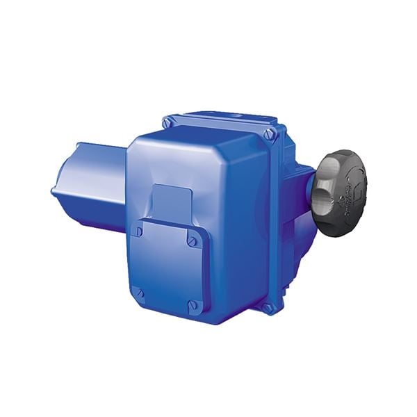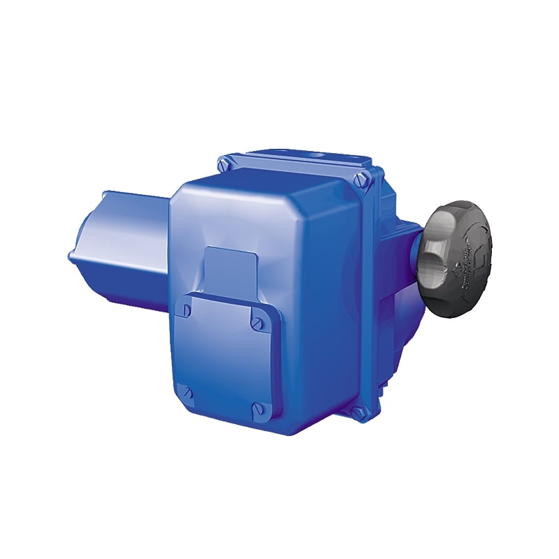
Electric actuator for On/Off, positioning or modulating of ball valves, butterfly valves or where a 90° rotation is needed.
| Torque | 45 Nm to 150 Nm |
|---|---|
| Drive | Electric |
| Article number | Amount |
|---|---|
| AT 3910-4 | |
| AT 3910-6 | |
| AT 3910-10 | |
| AT 3910-15 | |
| AT 3910-6X | |
| AT 3910-10X | |
| AT 3910-15X |

Weather-proof actuator for On/Off, positioning or modulating manuvering for ball- and butterfly valves. Torque from 45-150 Nm.
UEC.11 Actuator for valve, electric, two-position without spring return
Actuator Bernard Electrical AT 3910 for 90° maneuvering of ball valves, butterfly and where a 90° rotation is needed.
The actuator is manufactured according to desired properties, contact Armatec for more information.
CE marked
EC directives 2004/108/EC, 2006/95/EC, following the standards of EN 61000-6-4, EN 61000-6-2, EN 60034-1 och EN 60529.
IP 67 rated
| Detail | Material | Surface treatment | |
|---|---|---|---|
| 1 | Body | Aluminum | Zinc primer, epoxylayer and RAL 5002 blue polyurethane top coat |
| 2 | Cover | Aluminum | Zinc primer, epoxylayer and RAL 5002 blue polyurethane top coat |
| 3 | Drive shaft | Massive steel | Untreated |

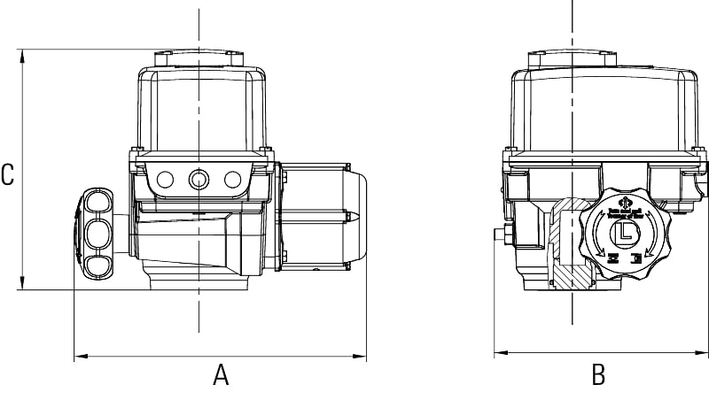
| Actuator / Fig nr | Drive shaft* | A | B | C | D | E | F | G | H | Weight | |||||||||||||||||||||||||||
|---|---|---|---|---|---|---|---|---|---|---|---|---|---|---|---|---|---|---|---|---|---|---|---|---|---|---|---|---|---|---|---|---|---|---|---|---|---|
| 3910-4 | Depending on valve | 273 | 200 | 225 | 116 | 73 | 74 | 40 | 95 | 6 | |||||||||||||||||||||||||||
| 3910-6 | Depending on valve | 319 | 200 | 225 | 116 | 73 | 74 | 40 | 95 | 7 | |||||||||||||||||||||||||||
| 3910-10 | Depending on valve | 319/362 | 200 | 225 | 116 | 73 | 74 | 40 | 95 | 7 | |||||||||||||||||||||||||||
| 3910-15 | Depending on valve | 362 | 200 | 225 | 116 | 73 | 74 | 40 | 95 | 7 | |||||||||||||||||||||||||||
| Dimension in mm, weight in kg. *Possible to get in requested size, parallel, keyway or a 45° rotation. | Dimension in mm, weight in kg. *Possible to get in requested size, parallel, keyway or a 45° rotation. | ||||||||||||||||||||||||||||||||||||
| Actuator / Fig. no | Drive shaft* | A | B | C | D | E | F | G | H | Weight | |||||||||||||||||||||||||||
|---|---|---|---|---|---|---|---|---|---|---|---|---|---|---|---|---|---|---|---|---|---|---|---|---|---|---|---|---|---|---|---|---|---|---|---|---|---|
| 3910-6X | Depending on valve | 454 | 200 | 225 | 116 | 73 | 74 | 25 | 95 | 7 | |||||||||||||||||||||||||||
| 3910-10X | Depending on valve | 454/497 | 200 | 225 | 116 | 73 | 74 | 25 | 95 | 7 | |||||||||||||||||||||||||||
| 3910-15X | Depending on valve | 497 | 200 | 225 | 116 | 73 | 74 | 40 | 95 | 7 | |||||||||||||||||||||||||||
| Dimension in mm, weight in kg. *Possible to get in requested size, parallel, keyway or a 45° rotation. | Dimension in mm, weight in kg. *Possible to get in requested sizes, parallel, | ||||||||||||||||||||||||||||||||||||
| Actuator / Fig. no | Drive shaft* | A | B | C | D | E | F | Weight | |||||||||||||||||||||||||
|---|---|---|---|---|---|---|---|---|---|---|---|---|---|---|---|---|---|---|---|---|---|---|---|---|---|---|---|---|---|---|---|---|---|
| 3910-6-6A3P | Depending on valve | 319 | 389 | 305 | 116 | 73 | 74 | 14 | |||||||||||||||||||||||||
| 3910-15-8A3P | Depending on valve | 362 | 389 | 305 | 116 | 73 | 74 | 14 | |||||||||||||||||||||||||
| Possible to get in requested size, parallel, keyway or a 45° rotation. | Dimension in mm, weight in kg. *Possible to get in different sizes | ||||||||||||||||||||||||||||||||
Standard version
Reversible actuator in four different sizes for 90° movement, adjustable through a combination of cams, mechanical end stop and/or torque switches.
The actuator is a compact combination of an electric motor with thermal protection and a self-locking worm gear. As standard with a hand wheel and position indicator.
The actuator mounting dimensions in relation to the fittings are according to ISO 5211.
Vibrations resistant to 1 g, (9.8 m / s2) at 10-500 Hz.
Design lifetime 20 000 cycles for On/Off or 300 000 starts for positioning. Tested according to EN 15714-2 class A and B
| Standard performance | ||||
| Motor duty | S4-30% ED, 360 starter/h max. S4-50% for modulating class III S4-100% for continues modulating | |||
| Enclosures | IP67, IP 68 optional, EX classified as optional | |||
| Temperature | -20°C to +60°C | |||
| Anti condensation heater | Included as standard | |||
| Thermal overload protection | Thermostat | |||
Permanently lubricated gear | Yes | |||
| Cable entries | Depending on actuator model | |||
| End travel switches | 4 as standard | |||
| Torque switches | No | |||
| Terminal block | 8 connections | |||
Actuator 3910 on/off | Torque Nm | Operating time (50 Hz) s | ISO-connection | 230 V AC 50 Hz Ampere | 400 V AC 50 Hz Ampere | 24 V DC | 24 VAC | ||||||||||||||||
|---|---|---|---|---|---|---|---|---|---|---|---|---|---|---|---|---|---|---|---|---|---|---|---|
| Stop | Stop | Start | Stop | kW | Start | Stop | kW | Operating time | Operating time | ||||||||||||||
| 4 | 45 | 45 | 6* | F05/07 | 0,9 | 0,8 | 0,03 | - | - | - | - | 6 | |||||||||||
| 6 | 60 | 60 | 6* | F05/07 | 0,9 | 0,6 | 0,03 | 0,5 | 0,3 | 0,03 | 6 | 6 | |||||||||||
| 10 | 100 | 100 | 6, 35, 60 | F05/07 | 1,7 | 1,2 | 0,06 | 1,1 | 0,6 | 0,10 | 35 | 35 | |||||||||||
| 15 | 150 | 150 | 15, 25 | F05/07 | 0,9 | 0,6 | 0,03 | 0,5 | 0,3 | 0,03 | 15 | 15 | |||||||||||
| *Other times on request | |||||||||||||||||||||||
Standard version, see above.
Possible options and variants
Actuator Intelli+, see seperate datasheets for possible features, such as summer alarm, bus-control, travel-time control etc.
Power supply 3-phase
380/415 V - 50Hz, 440/460 V - 60 Hz
230 V - 50 Hz, 220/230 V - 60 Hz
500 V - 50 Hz eller 5775 V - 60 Hz
1-Phase
110, 115, 120, 220 V - 50 Hz
115 V-60 Hz
24V - 50 Hz
DC
24, 48, 110 or 220 VDC
For other time periods, contact Armatec
For off-shore painted actuators, contact Armatec
For ATEX-rated actuators, contact Armatec
During all work with the actuator the power MUST be disconnected.
- The actuator must be connected as per the wiring diagram, see the manual.
- Each actuator must be powered by an individual switch or relay contact, minimum 16A, to prevent cross-feed between the actuators.
- At outdoor installation, the actuator should preferably be protected by a roof or cap.
- Installation with the motor downwards should be avoided.
- Turn the valve with the control unit's hand wheel to centre position. See indication on top of the device.
- Always connect the heater.
- Check that the actuator turns the valve in the desired direction.
- The correct limit switch (open or closed) shall break the motor current.
- Cable entries must comply at least to the lowest protection class of devices.
See the manual for start-up, storage and maintenance.
Article number, manufacturer, serial number, voltage and current.
Wiring diagram is placed by the motor at delivery.
| Control signal | 230 V, 50 Hz | 3-phase 400 V, 50 Hz | 24 V |
|---|---|---|---|
| 4-20 mA or 0-10 V | Minigam, Integral, Posigam | Intelli, Integral, Posigam | Intelli, Integral, Posigam |
| Profibus DP | Intelli, Integral, Posigam | Intelli, Integral, Posigam | Intelli, Integral, Posigam |
| Example: 3910-4-3A3A | |||||
| AT3900 | -4* | 3** | A*** | 3**** | A***** |
| Fig. no | Size | Operating time | Connection | Voltage | Options |
| * 4, 6, 10 or 15 depending on needed torque | |||||
| ** =Time: 3s, 2=5s, 3=6s, 4=10s, 5=15s, 6=20s, 7=25s, 8=30s, 9=35s, 10=45s, 11=50s, 12=60s | |||||
| *** A=F05/07 | |||||
| **** 0=24 VDC, 1=24 VAC, 3=230 VAC, 4=400 VAC | |||||
| ***** A=On/Off, B=Integral, C=Posigam, D=Minigam, E=1000 ohm POT, P=Intelli+ |